Extinguishing Oil And Gas Fires
The Well Fire Problem
Blow-outs are relatively common for onshore and offshore oil and gas wells. Offshore data collection by the Hazardous Installations Directorate of the UK Health and Safety Executive over the period 1992-2002 identified 2312 hydrocarbon release incidents of which 147 were classified as major and 1284 as significant. These led to 42 gas ignitions, 17 of which were classified as significant, and 101 liquid ignitions, of which 24 were classified as significant. Although the majority of blow-outs worldwide do not lead to major fires, at least ten per year are serious fire hazards which have the potential to destroy the economic viability of the well in question. Oil blow-outs can generate large scale jet flames with flame heights of typically 20-70 metres and heat radiation emissions in the range 90 megawatts to 2 gigawatts. Current methods of extinguishing onshore oil or gas flares are crude in operation. They aim to blowout the whole flare column and will often employ large dynamite charges or large scale foam or bicarbonate powder smothering. If such an attempt is unsuccessful, the whole operation has to be started from scratch. Since large charges (typically 250 kg) are required, the operation itself is a major hazard and specialised teams are required. The equipment required by such teams is large and heavy machinery and most of the time spent in well control is taken up with the handling and transport of such equipment. Furthermore, such operations are not feasible on offshore rigs because of the danger to rig structures. Only water and conventional firefighting resources are currently available for dealing with rig flares. The use of water is the most important method for limiting fire damage and sprinkler heads and deluge nozzles are standard equipment on modem offshore rigs, where pumped water is readily available.
A particular difficulty in devising techniques for extinguishing flames is that little information is available on the detailed physical characteristics of the flame, since because of the extreme radiation levels, it is not possible to site diagnostic instrumentation close enough to the flame without damage to it. The radiation from a large oil well flare of some 70 metres height (corresponding to an oil flow of up to 30,000 barrels of oil per day) can give temperatures of 500 C at ground level some distance from the base of the flare. On the other hand, it is clear that the physical structures of oil and gas flares can be predicted in terms of scale-up of the known physical structures of turbulent jet diffusion flames, the fuel jets of which entrain air as oxidant by virtue of their jet momentum. The point of attachment of a flare is critical in maintaining a stable flame structure. The characteristics of the fluid flow at the base of the flare are determined by the geometrical characteristics of the breakup of pipe work at the well head.
Oil and gas flares are large but relatively simple turbulent jet flames. Gas velocities in the body of the flare are very high and, without a mechanism to stabilise the base of the flame on the pipebreak, the whole flare would lift off the pipe and might well extinguish itself a few metres above the break. A necessary mechanism for flare stabilisation at its base must involve the creation of a low gas velocity volume close to the pipe break. There are two fluid dynamic regimes which provide this mechanism. The first involves the setting up of a gas recirculation zone in the region of the pipe break. This is the most common stabilising phenomenon for turbulent flames. Whereas in the body of the flare the mean gas velocity vectors lie parallel to the axis of the near-cylindrical geometry of the flare, the velocities in the recirculation zone are low and even oppose the main flow in parts of the flow field. The second regime involves swirl, where the flow vectors at the flare base are usually nearly at right angles to the main flow. This provides a second mechanism for diverting flare momentum into a relatively low flow region and therefore assists in the base stabilisation process. Figure 1 illustrates the processes of flow recirculation and swirl which will occur at the base of a flare. The novelty of the present invention is that it provides a means of generating a supersonic jet crossflow into the base of the flare to essentially disrupt the stabilising region and in effect to blow it away. Thus extinguished, the base flows can no longer stabilise the burning flare on the pipe break and the flare must necessarily blow off. A second novel feature of the invention is that it provides a means of repetitively generating the supersonic crossflow jet, thus obviating re-ignition of the flare by the hot pipework. One-shot techniques such as those using explosives do not have this advantage and here ifre- ignition occurs, the extinguishing operation has to start again from scratch.
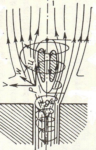
fig 1
The shock wave firefighting device
This invention is a device for repetitively generating pulsed fluid flows up to supersonic velocities and directing them in a focused manner at the base of the flare column where gas recirculation and swirl predominate. The net result is that the relatively low flows of fluid in the flame stabilization zone are augmented by the high velocity pulsed flow to such an extent that the flame must necessarily detach from its fuel supply base and the flare extinguishes. Broken wellhead pipework will usually lead to discharge orifices at the base of the flare of 0.15-0.30 metres diameter. The pulsed supersonic flow generator described here gives supersonic fluid pulses in a fluid column of typically 0.05 metres diameter. In terms of volumetric flow rate, this is well in excess of the mean flow rate of oil or gas from the blow- out. The device also operates repetitively and this feature of the device is essential for the prevention ofre-ignition at the base of the discharging hydrocarbon column. The essential features of the device are illustrated in Figures 2 and 3. The critical element in the device is a shockwave valve A which, when closed, separates a high pressure gas of high specific heat ratio (the driver gas) from a fluid of low specific heat ratio at atmospheric pressure. The driver gas is contained in a cylindrical chamber B around which is an annular chamber C, both of which are connected by bleed holes G. On the other side of the shock wave valve is the cylindrical discharge tube D, which is 2 metres long and at least 0.05 metres in diameter. These dimensions are important since the discharge tube length must be sufficiently great to allow shock wave development in the tube and the tube diameter must be large enough to avoid excessive fluid boundary layer growth on the inside surface of the tube, which could lead to a degeneration to low velocity pipeflow in the tube without shock formation. The shock wave valve shuttle which separates the driver gas from the discharge tube moves in a cylindrical guide F and the fluid-tight seal between the driver gas and the discharge tube is maintained by an 0ring seal. A light coiled spring holds the front face of the shuttle on its O-ring seal prior to operation. The device is operated by first pressurizing the driver gas chamber Band the annular chamber C with helium, which has a specific heat ratio of 1.67, to a pressure typically in the range 100- 250 bar (10-25 megapascals) with the shock wave valve shuttle A seated on the O-ring seal. The opposite end of the driver gas chamber is also sealed by a valve S capable of rapid release of the helium to the external ambient atmosphere. The design of this gas release device is not critical and can be a solenoiddriven exhaust valve, such as those used for offshore seismic exploration, or a motordriven eccentric earn-operated O-ring sealed shuttle valve or any other conventional design of gas-release valve capable of being operated repetitively under high gas pressure conditions.
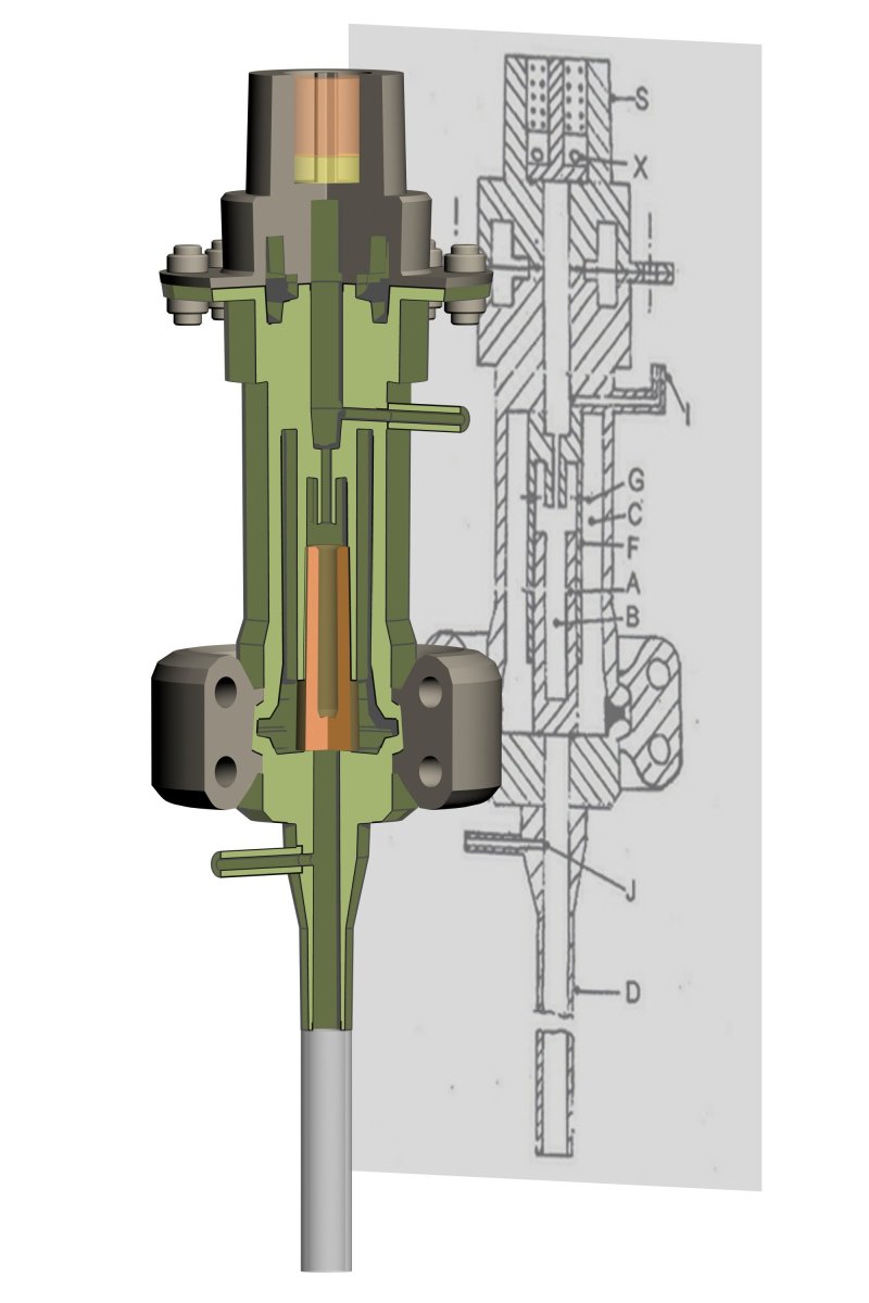
fig 2
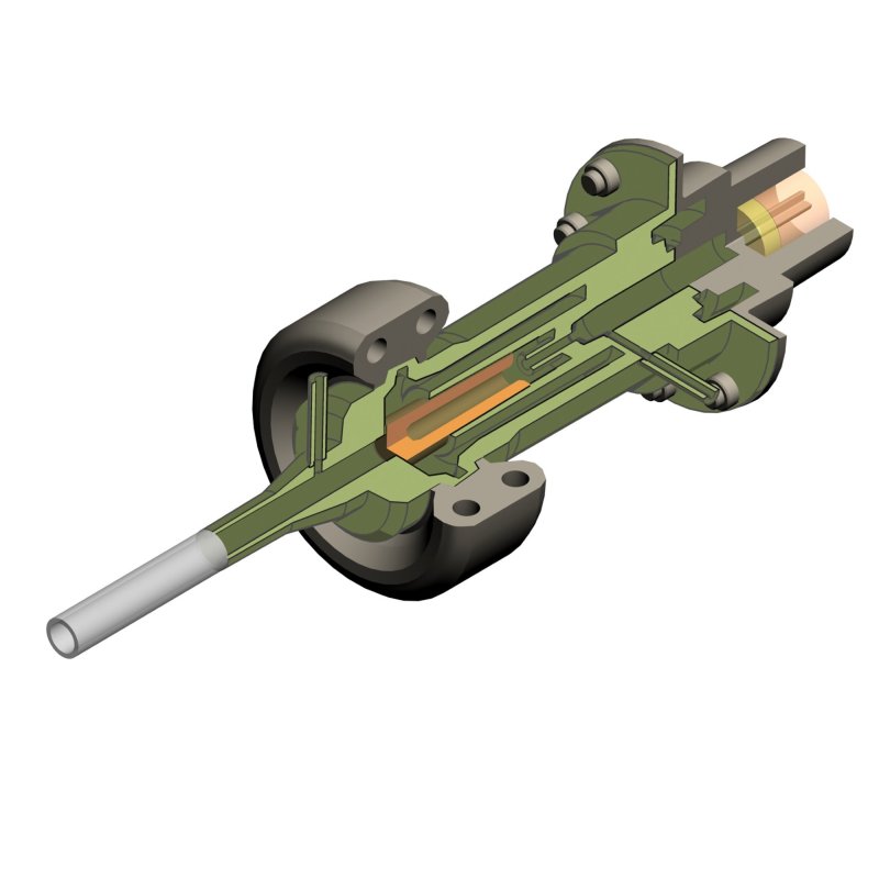
fig 3
The open-ended discharge tube D is the part of the device in which the shock wave is generated. Because of the high radiation conditions under which the device is operated, the discharge tube is constructed of stainless steel or, preferably for extreme conditions, of titanium. A small-diameter inlet tube J provides the route by which a continuous stream of fluid at ambient pressure is fed into the discharge tube. The fluid can be air or nitrogen or any other non-flammable gas or it can be water. For air as the fluid, a simple low-pressure air pump is the driving device. In order to generate maximum shock strengths in the discharge tube, it is important to keep the temperature of the fluid in the discharge tube as low as possible. This can be best achieved by providing external cooling to the external surface of the tube. Various options are available. The tube may be wound with a pipe coil through which water or air is pumped or the tube may be jacketed and coolant continually circulated through the jacket. An additional option is to provide refrigeration for the coolant. This may be achieved by a simple conventional refrigeration closed cycle i.e. using ammonia or freons or it may be achieved by solid state Peltier refrigeration devices built into the coolant line. The typical mode of operation of the device is as follows. With the solenoid valve closed, the driver gas chamber and the connected annular chamber are pressurized with the inert gas helium to a pressure normally in the range 100-250 bar (l0-25 megapascals). Helium is the driver gas for shock wave generation and it is chosen for its high ratio of specific heat at constant pressure to that at constant volume. The only other effective alternative as a driver gas would be hydrogen, which, being flammable, is too hazardous for use in these conditions. During or after helium pressurization, the air pump flushes a continuous stream of air through the discharge tube. The solenoid valve is then opened electrically to instantaneously release helium to the ambient atmosphere via its exhaust ports and the shock wave valve shuttle accelerates immediately off its O-ring seal separating it from the discharge tube. Because the high pressure helium in the annular chamber acts as a reservoir of driver gas, a high pressure of helium is maintained in front of the shuttle as it accelerates towards the rear of the driver gas chamber. The net result is that a transient step discontinuity in pressure is formed at the interface between the section of the driver gas chamber in front of the shuttle and the atmospheric pressure air in the discharge tube. This is the condition for the formation of a near-plane shock wave with a gas velocity behind the shock front typically in the range 660- 1500 metres per second. The supersonic jet of air then emerges from the open discharge tube, expanding slightly in diameter in line with the well-established gas dynamic rules for shock diffraction. With the exit point of the discharge tube at reasonable distance from the base of the well flare, typically 5-10 metres, the shock-driven gas jet is directed at the base flow in the flame. The total gas momentum in the jet from one shot is a substantial fraction of the flare gas momentum and will detach the flare from its stabilizing region, thus extinguishing the flame. Re-ignition of the flare by the hot pipework is a possibility, so it is important that the shock- generating device operates repetitively. This condition is easy to achieve with an exhaust valve capable of repetitive operation, such as the solenoid valve or any other conventional pressure release valve which can operate automatically through the required pressure cycle. A repetition rate of six shock wave pulses per minute is easily achievable. The device also makes provision for the use of a water jet as the extinguishing fluid. In this mode of operation, water is pumped in a continuous stream through the discharge tube inlet to form a jet which plays on the base of the flame. By itself, this jet is not capable of extinguishing the flame. However, if the device is then operated as described above with helium pressurization of the driver gas chambers and the annular reservoir chamber, followed by instantaneous opening of the shock wave valve via the solenoid valve exhaust system, a near-transonic acoustic wave will form in the water stream in the discharge tube. The physics of the process is such that the fluid velocity behind the shock wave is close to the velocity of sound in water, 1500 metres per second. Because of this high velocity and the high density of water, the base of the flame is subjected to a substantial increase in fluid momentum, quenching the stabilizing region and blowing off the flare. Subsequent to this, the un shocked water jet will help to cool down the hot pipework and probably also generate steam in the pipe break area. The net result is that re-ignition is unlikely, although the device would be operated repetitively to ensure that re-ignition is ruled out.
A third mode of operation is to operate the device with air and water alternately as the shocked fluids. This mode has the advantage that a shorter cooldown period is possible than with air alone as the shocked gas, thus cutting down on the number of repetitive pressurizations and depressurisations necessary to extinguish the flare permanently. A fourth mode of operation would be to operate the device with nitrogen instead of air as the shocked fluid. This has the advantage that a nitrogen gas cloud could be built up as an inert gas shield around the pipe break, thus minimizing the possibility of re-ignition. Here, the shock wave properties of nitrogen in the discharge tube stream would be very close to those of air and the mode of operation and effect on the base flow in the flare would be similar to those described above for air. For this mode of operation, it would be essential to maintain supplies of nitrogen on site. This could be readily achieved by having a store of the gas in high-pressure cylinders.
A fifth mode of operation would be to operate the device with carbon dioxide as the shocked fluid. This has the advantage, as with nitrogen, that an inert gas shield can be built up around the pipe break. On some well sites, carbon dioxide is readily available as a reservoir fluid by- product or as the means by which enhanced oil recovery from partially-depleted wells is achieved. An alternative source, if refrigeration is available on site, would be to store carbon dioxide in solid form.
In all these five modes of operation the exit point of the discharge tube needs to be relatively close to the base of the flare if the greatest advantage is to be taken of the focusing of the shock wave-driven jet into a narrow beam. A typical range of distances would be 2-10 metres, depending on the size of the flare and its radiative emission intensity. At such distances, radiation protection for the device is needed, particularly for large flares. The provision of radiation protection for instrumentation and personnel is a common requirement for firefighting on well blow-out sites. The present device can be mounted on a mobile carriage with firebrick insulation at the front of the carriage and aluminium or other radiation-reflecting sheeting on the front face of the firebrick shield. A small aperture in the shield is sufficient for the discharge tube exit with the whole of the device thermally-protected. The carriage can be automated to be operated remotely in a conventional manner, as either an electrically-powered vehicle or as a carriage which is positioned mechanically by the use of an external boom. Since experimental results on the physical characteristics of the supersonic jet would be very difficult to obtain, it has been necessary, in order to generate a detailed understanding of the operation of the device, to model the supersonic jet characteristics using established principles of gas dynamics by way of computational fluid dynamics modelling. Standard commercial computational fluid dynamics packages are of little use for such modelling since their strengths lie in the areas of solving partial differential equation sets for boundary layer (so-called parabolic) flows or re-circulating (elliptic) flows. The fluid dynamic partial differential equations for the supersonic flows in question here are, in mathematical terms, hyperbolic partial differential equations, for which special methods need to be developed. We have concentrated on developing a computer package for modelling the fluid flow in the device and external to the discharge tube using the Piecewise Parabolic Method (PPM), which is a modem computational technique specifically designed to solve the hyperbolic partial differential equations describing shock wave generation. Extensive computation has been carried out for various conditions of operating the shock wave device. One example of the results obtained is shown in Figures 4A and 4B. The discharge tube has been assumed to have a length of2 metres with an internal diameter of 0.05 metres. The helium pressure for the driver gas is 100 bar (10 megapascals) and the gas column in the discharge tube in which the shock wave is generated is air at 1 bar pressure. At the point of exit from the discharge tube the shock wave is effectively plane with a gas velocity behind the shock front of Mach 1.6-1.7. After the shock wave has left the discharge tube, Figure 4A shows that a double- peaked shock wave forms with an axial velocity behind the shock front in excess of Mach 2 up to a 5.5 metre distance and over the 0-0.025 metre range of tube radius. At this axial distance, even outside this core flow and in the region of expanded gas flow, an axial direction supersonic flow of circa Mach 1.2 is preserved. This general picture contrasts markedly with that for radial velocity flow i.e. flow expansion outside the flow discharge tube (Figure 4B). Within the discharge tube, the radial flow velocity is effectively zero. In the region of expanded flow outside the discharge tube, the radial velocity only reaches a maximum of 60 metres per second at the 5.5 metre point. The net conclusion from these predictions is that under the conditions of operation specified as an example the device produces a supersonic core flow as a mainly focussed jet, with only a minor subsonic radial expansion flow accompanying it.
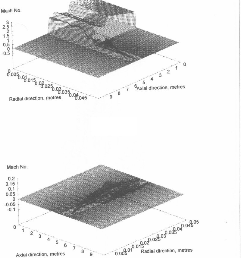
figures 4a, 4b